TOOL CHARACTERISTICS TO SUPPORT ALL LIFECYCLE STAKEHOLDERS’ REQUIREMENTS IN COLLABORATIVE ENGINEERING DESIGN
par Maria Paz Claros Salinas, Guy Prudhomme and Daniel Brissaud
3S Laboratory, University of Grenoble, BP 53, 38041 Grenoble cedex 9
DET06, Setubal, Portugal, 2006
This paper presents some work about characterization of tools that support designers on requirement management. Indeed, in concurrent engineering context, requirements management has become a complex task because requirements have to be taken into account as soon as possible in the design process. We analyzed the design process through different points of view. We built a three-dimensional grid to characterize requirement management tools. Our goal is to validate the capability of this grid to characterize and evaluate the capabilities and the lacks of requirement management tools on supporting designers during the design process.
1. INTRODUCTION
This work deals with the study of engineering product design, particularly industrial products. During the last years, the increasing market competition and pressure on quality, cost and lead-time have led to changes in the organizational mode of the industries. Indeed to tackle difficulties coming from competitiveness, the design process has become collective. The aim of this movement is to enable all the life cycle stakeholders to work together. A stakeholder of the design process is a person who is involved in the design process of the product, whatever his task is. In this way, most of industrial organizations have shift from a hierarchical structure to a more transversal one. Concurrent Engineering is a model of this new organizational mode, where the design process of a product is a collective and simultaneous activity: needs and constraints of the all life cycle stakeholders should be considered and studied.
This new organization mode implies the necessity of new methods development to efficiently structure the design process. The methods proposed by Palh & Beitz (Palh&Beitz, 1996) or Ulrich (Ulrich, 2000) describe the design process as the search of solutions to satisfy identified needs. In a concurrent engineering approach, synchronous activities alternate with asynchronous ones. In synchronous activities, designers work collectively to assess proposed solutions. In asynchronous activities designers work as experts in order to develop the solution or a part of it based on his discipline rules and experience. It is assumed here that the design process follows a co-evolutionary approach (Maher, 2003), (Lonchampt, 2006) in which problem and solution permanently evolve in a simultaneous manner.
In a co-evolutionary design process, we focus on the clarification process of the requirements so as to characterize the properties of the design tools that support designers on this clarification. Main questions are:
• What is called a requirement?
• What are the advantages and drawbacks of the commercial tools that are supposed to support designers in requirements expression throughout the design process?
• What properties should have those tools to support the requirement management?
This paper is organized as the following. In section 2, we will clarify the requirement concepts and terms and propose a first classification of requirements management tools. In section 3, the space of the design process properties is explored so as to highlight the 3 dimensions characterizing the requirement management tools. Some tools are treated through this space analyzer in order to illustrate the relevance of the grid analysis. We aim to evaluate its capacity to represent tools capabilities concerning designers support on taking into account requirements throughout the design process.
2. REQUIREMENTS IN AN INDUSTRIAL DESIGN PROCESS
2.1 Identifying the client
Many authors say that the design process consists in setting up activities to propose solutions to satisfy clients’ needs. Based on this definition, we add that these activities are bi-directional: from clients’ needs to solution and conversely. Let us define more accurately who the clients are in this process.
The first client that is mentioned here is the one whom the product is developed for. He generally does not belong to the organization, and is called ‘external client’. The term ‘needs’ in the literature is generally related to the external client.
In a Concurrent Engineering context, the viewpoints of each product lifecycle stakeholder have to be considered. Each of them defines his own specifications on the project. For example, the manufacturing expert and the recycling expert will explicit their needs on the product from their expertise to make the manufacturing process and the recycling concerns be easy and profitable. These life cycle product experts are called ‘internal clients’ since they are members of the ‘extended company’. Internal clients get the industrial organization point of view. The practical term for the internal client is ‘constraints’ instead of needs.
To sum up, a concurrent engineering context brings two kinds of clients whose needs and constraints should be integrated and tackled in an efficient design process:
• The external client initially formulates the needs concerning the product and reformulates them throughout the design process. As a consequence he is a stakeholder of the design process.
• The internal clients, industrial stakeholders of the design process, formulate their constraints. Those constraints may evolve throughout the design process.
Finally stakeholders of the design process can be internal clients, external clients or designers.
2.2 From needs to requirements
A literature review has been done to understand the terminology. The conclusion of this survey is a reformulation of the concepts to make them clearer in our mind.
The needs can be expressed by any stakeholder but mainly by the external client. It is a lack or an expectation expressed in a natural language. Very often external clients do not know how to express their needs and are not aware of both the interest and the techniques of their expression. It is generally assumed that most of the needs appear at the beginning of the design process.
For example, let us take the design of new car doors. The client would express his needs by “My car doors must have a good appearance and should be easy to open and close”.
A constraint is a restriction, a limit or a regulation imposed on a product, a project or a process. It is a type of prerequisite or design feature that cannot be trade off, a condition that has to be respected. These constraints are related to standards or rules proposed by external organizations or to expertise of downstream steps of the product life cycle stakeholders. It may also come from the business strategy of the company.
For example, at least 70 percent of the car components must be recyclable; or the door components should be manufactured by the company facilities.
The literature review lead us to different definitions of the requirement concept. American standards (IEEE, 1999) define requirement as “a statement that identifies a product or process operational, functional, or design characteristic or constraint, which is unambiguous, testable or measurable, and necessary for product or process acceptability (by consumers or internal quality assurance guidelines)”. For Harwell (Harwell, 1993) “a requirement is something that must be accomplished, transformed, produced, or provided”. Lin (Lin, 1996) defines requirement as “something that specifies the properties (functional, structural, physical, etc.) of the artifact being designed”.
The conclusion based on the review is that a requirement is a need or a constraint expressed in a standard language. It is expressed in terms that stakeholders can understand without ambiguities because the meaning has been previously discussed and shared. Let us mention that in the Concurrent Engineering context, a requirement is more than just a translation of the needs and constraints. It results from a long process of exchanges, discussions and negotiations among the stakeholders.
A requirement can be expressed by one sentence including “have to” or “shall be”. European standards propose functional language to explicit a requirement as a function with assessment criteria and levels associated. See Table 1 for continuing the example of the car doors specification process.
Table 1- Requirement Formulation (European Standards)
Of course, requirements will be evolving throughout the design project, as needs and constraints do.
3. THE THREE-DIMENSIONAL ANALYZER
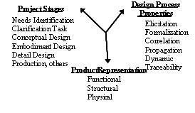
Requirement management tools are classified in three groups by industrialists: requirements definition assistant tools, that assist designers and engineers to define the requirements from the identification of the needs to the formal expression; requirements transformation assistant t ools, that assist designers to follow–up and support the transformation of requirements during the design process; requirements monitoring assistant tools, that assist designers to regulate, control and check requirements throughout the design process. This classification is too loose for a good characterization of requirement management tools. In this section, we aim to present the three-dimensional space highlighted by our work in order to analyze the performance of requirement management tools throughout the design process. The three dimensions are: the project view, the representation of the product and the design process properties. They are described in detail in the following.
3.1 The project stage dimension
This dimension is a project management view of the design process. Most of the companies organize their work by projects. A project is a temporary endeavor undertaken to create a product or a service. It includes a deadline and, from a management viewpoint, goes from a milestone to the next. So this dimension contains the different stages of a project, which will be separated by assessments or decisional meetings. According to Palh & Beitz, the first stage of a design process is to identify the needs. At the end of the second stage, called clarification of the task, requirements have to be defined. Then the following stages are : conceptual design phase in which designers propose structural solution; embodiment phase in which a mechanism description has to be proposed; detail design phase to define parts; industrialization to define production process; etc.
This project view is useful for design process management. This axis is therefore relevant to identify which stage of the project is supported.
3.2 The product representation dimension
During the project development, designers use different product representations: functional, structural and physical ones. At the beginning of the design process, the representation of the product is mostly functional, then it turns to structural representation and finally to physical representation. The product representation passes from an abstract representation to a concrete one. Yet, from a cognitive and co-evolutionary point of view, this evolution does not happen sequentially (Darses, 1997): the designers work simultaneously on the three representation levels, zigzagging across those levels. This axis is relevant to identify the type of representation supported.
A Functional Representation includes functions that the product must fulfill and constraints that has to be respected. Functions and constraints are characterized by associated criteria and levels. Functional representation is an external description of an answer to the customer’s demand. It can also be a technical description of the functional possibilities to fit the external functions. For example, a specification list or a QFD matrix are both considered as functional representations.
A Structural Representation describes the possible structure of a product. It can be a schematic representation, like a cinematic scheme, or a diagram including components and links among them. A block diagram coming from the value analysis methodology is a good example of structural representation.
A Physical Representation describes geometrical and technological properties of the product. Numerical representations in CAD tools, prototyping are included in this representation level.
3.3 The properties of the design process dimension
This axis is relevant to identify the capabilities to support the properties of the design process. As mentioned at the beginning of the paper, the design process is no longer an individual work but a collective one. In a Concurrent Engineering context, the team of designers is composed of people coming from different companies and expertise fields. Each one has his own viewpoint and requirements concerning the product. Each one expresses his needs to the team, who has to build a common understanding (processes of elicitation and formalization). Once the first level of requirements is formalized, designers use them as baselines to look at the solutions. But these requirements are not definitively fixed since they are co-evolving throughout the design process, depending on new constraints and candidates. The stakeholders who are concerned by the requirement changes must be aware of them: the design process has properties of dynamics and propagation. And of course requirements should be consistent at any time of the design process (properties of correlation) and across product families (properties of traceability).
This axis is composed of the six main properties of the design process: elicitation, formalization, propagation, dynamic, correlation and traceability processes.
Elicitation : Eliciting means to bring something out, calling forth or drawing out (information or response). Methods are needed to help designers to be the more rigorous and exhaustive during this activity. For example 6WH method (Who, What, When, Which, Why, Where, How) can be seen as a possible method helping designers to elicitate requirements.
Formalization : Formalization is the action of setting requirements in a formal language. This language must enable all stakeholders to express their own requirements, to share viewpoints and to negotiate. Functional analysis is a formal language standing for being a method to help designers to formalize requirements.
Propagation : Requirements at different stages of the design process are not independent from each other but they relate to each other. The propagation is the capability to build relations between the requirements and to propagate the impact of changes onto impacted requirements, upstream and downstream in the design process.
Dynamic : A requirement can be added or removed from at any stage of the design process: the list of requirements is dynamic. The consequence is that new dependence links are going to appear and disappear. This connection between requirements impacts the possibility of creating or giving up requirements while designing. The Quality Function Deployment method can support the property of criteria propagation thanks to the matrix relation. Unfortunately these matrixes are static ones because requirements cannot easily and quickly be added or removed.
Correlation : The correlation is a relationship between requirements at the same stage of the design process. Correlation is the relation between two variables varying one according to the other. The roof of the QFD matrix enables designers to make this sort of correlation.
Traceability : Requirements should be traced forward from an initial statement to specifications and design components, and backward from design components to their motivating requirements. Backward tracing is necessary for system modification and maintenance, while forward traceability is used in managing development from requirements to implementation. Traceability is the ability to trace the history or location of an entity by means of recorded identifications.
The content of the three-dimensional analyzer is summarized on figure 1.
Figure 1- Three-dimensional analyzer content
4. APPLICATION OF THE ANALYZER
Let us apply the three dimensional analyzer on two commercial tools of requirement management. It will help the understanding of the analysis framework and highlight the properties that are not covered yet.
4.1 Project Stages
TDC Need software ® : The first information to introduce in the tool, addresses the project definition. Designers must answer a list of questions coming form the AFNOR standards (AFNOR, 1990), (AFNOR, 1991). Then, the identified needs are expressed in the form of functions. Those functions are formalized in the characterization table proposed by the Functional Analysis method. TDC Need® is positioned on the two first stages of the axis.
DOORS®: Baseline requirements must be identified and defined before beginning the work on DOORS®. Those requirements are introduced in DOORS®. Then, designers can use the tool to support requirements evolution in other stages of the project. It covers most of the stages of the axis.
4.2 Product representation
TDC Need ® mainly supports the functional representation of the product because of the external Function Analysis method. This functional representation only addresses the first level of the product requirements definition: the external clients needs expressed with functional terms.
DOORS® supports the functional representation of the product allover the product life cycle.
4.3 Properties of the design process
TDC Needs®: The design method included gives the capability to support designers on the requirements expression and formalization to the tool. It allows to save the different versions of the requirements. Those traceability and propagation properties only address the functional aspect.
DOORS®: This tool is able to support the designers during requirement formalization. It also helps to define the links between requirements and allows propagation. DOORS® enables the designers to have a general view over the changes and evolutions (add, change, delete…) of requirements.
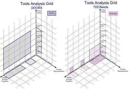
Figure 2- TDC Need® and DOORS® on the three-dimensional analyzer space
These properties are summarized in Figure 2. The analyzing space proposed is more accurate than the rough classification made by the industrials. Indeed, according to their classification, Requirement Definition tools spot the intersection between Elicitation and Needs Identification; Requirement Transformation tools spot several categories of the space; Requirement Monitoring tools spot the surface between Project Stages and Design Process. As visualized on Figure 2, the two tools do not support the same activities: DOORS® is mainly a Requirement Monitoring tool and TDC Needs® a Requirement Definition tool. Both of them mainly address the functional representation of product. They are complementary tools and do not cover the whole space together.
5. CONCLUSION
This paper started with three main questions. The first one was about requirements definitions. Our answer is that a requirement is a formal expression of a need or a constraint expressed by any stakeholder of the design process. The next two questions can be answered together. The characteristics that requirements management tools must support have been extracted and structured in a three dimensional space: project management, product representation and design process properties. These three axis and the values proposed on each of them, enable us to analyze and identify tools capabilities and consequently their lacks. The first applications of the analyzer give us relevant information.
The issue now is to propose a exhaustive list of specifications for a computer-aided tool supporting the whole cycle of requirement management throughout the design process. As seen on Figure 2 a wide part of the space is not addressed so far and the properties that must be covered have to be documented and implemented.
6. REFERENCES
- 1. Darses Françoise, “L’ingénierie concourante: un modèle en meilleure adéquation avec les processus cognitifs de conception”, Ingénierie concourante de la technique au social, 1997, ISBN: 2-7178-3498-2
- 2. Harwell R., Aslaksen, E., Hooks, I., Mengot, R., Ptack, K., “What is a Requirement?” in Proceedings of the Third International Symposium of the NCOSE, 1993. Retrieved September 2001, from https://www.incose.org/rwg/what_is.html
- 3. Jinxin Lin, Mark S. Fox and Taner Bilgic, “A Requirement Ontology for Engineering Design”, Enterprise Integration Laboratory, Dept. of Industrial Engineering, August 1996
- 4. Pahl G. and Beitz W., Engineering Design: A Systematic Approach, Springer Verlag, 1996 (2nde éd.).
- 5. Lonchampt P, Prudhomme G, Brissaud D, “Supporting Problem Expression within a Co-Evolutionary Design Framework”, in Advances in Design, ElMaraghy, Hoda A.; ElMaraghy, Waguih H. (Eds.), pp 185-194, Springer, 2006, ISBN: 1-84628-004-
- 6. Maher M.L., Tang H.T., “Co-evolution as a computational and cognitive model of design”, Research in Engineering Design, 14, 1, 2003.
- 7. Software Engineering Standards Committee of the IEEE Computer Society, IEEE Std 1220-1998, IEEE Standard for Application and Management of the Systems Engineering Process, January 1999, p34-42. Retrieved October 2001,
- 8. Ulrich K.T. and Eppinger S.D. , Product design and development, Second edition, McGraw Hill International editions, 2000
- 9. AFNOR NF X 50-150, Vocabulaire de l’analyse de la valeur et de l’analyse fonctionnelle, Association Française de Normalisation, 1990
- 10. AFNOR NF X 50-151, L’analyse fonctionnelle, Association Française de Normalisation, 1991


