Save a significant amount of time for your teams!
With Infra CONVERT, avoid mistakes while copying dimensions or specifications in your FMEA studies!
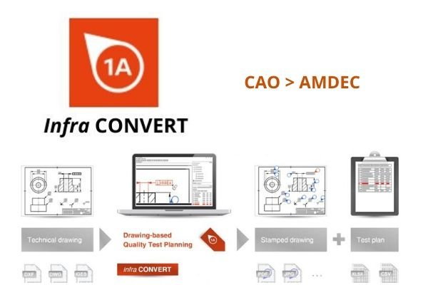
The Infra CONVERT module allows you to open a CAD drawings, to analyze it, and then automatically extract all dimensions you want (dimensional and geometrical specifications).
Then characteristics will be used to:
- your Design FMEA: the characteristic complements the functional analysis to identify customer requirements
- your Process FMEA: use dimensional and geometrical specifications as inputs of your Process FMEA to accurately identify failure modes
- following the Process FMEA, the control plan is built with the imported characteristics
- work instruction which is based on the control plan
- control range being based on the control plan, information is followed from the customer plan to your control strategy.
CAD to FMEA: key points of Infra CONVERT
- Ensure feature recognition rates up to 100%. You can retrieve specifications without error with just a few mouse clicks using the previously loaded symbol tables.
- Always do the link with quality documentation thanks to numbered marker on your drawings. Marking allows you to maintain a dynamic overview. By comparing plan versions, you can easily evaluate the impacts without having to start from scratch
- Reduce the time required to process plan’s data by up to 70%.
- Integrate Infra CONVERT as a module in a CAD system.
- User interface is intuitive and reduces training time.
Which extractions are available from CAD?
- List of specifications selected to be processed later in FMEA, in the Control Plan or in the Work instruction, or even in MS Excel.
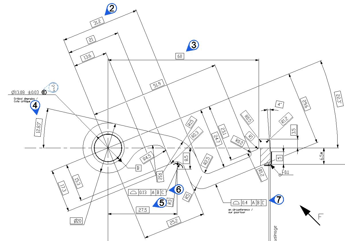
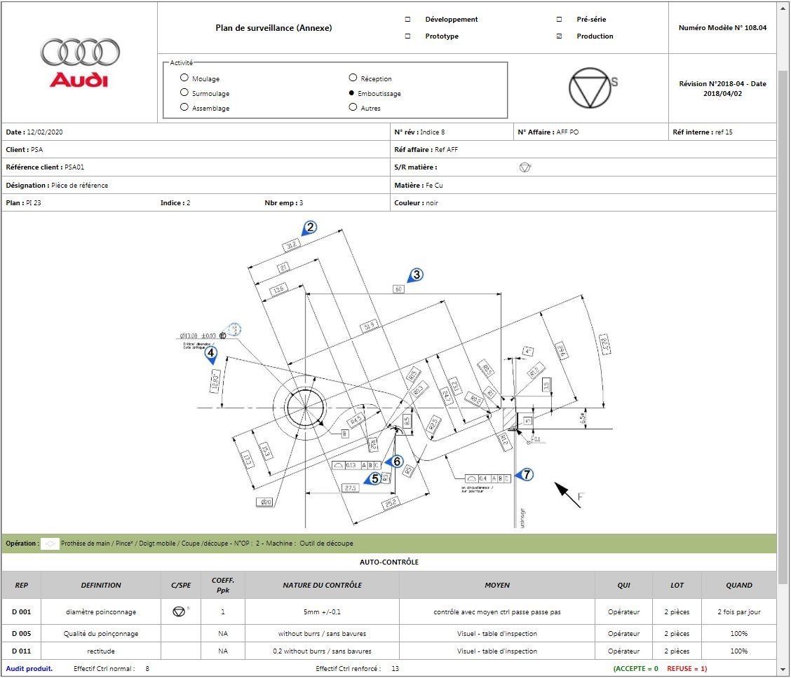
- Marked plan (stamp) is available as a PDF File or as a picture that may be integrated in the work instruction.
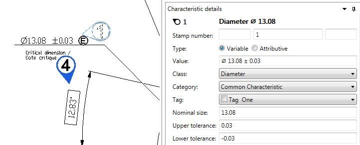
- Structured decomposition of the specification: stamp number, type (variable, attributive), value, class, category, designation, nominal size, upper and lower tolerance, tolerance class, and reference (isostatic).
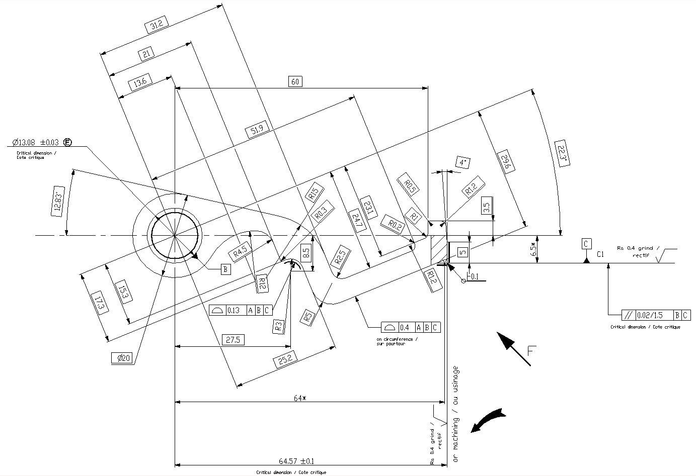
Example of a marked plan (stamp)
Example of the specifications’ decomposition
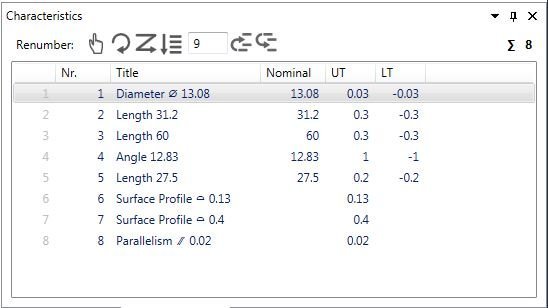
Characteristic properties
Import of specifications from your technical drawing into Infra Convert
Use pictures of the marked drawing in the work instruction
What are CAD drawings managed by Infra CONVERT?
- Drawings in an exchange CAD format (DWG, DXF or IGES)
- Drawings in another format (PDF, TIFF, PNG, …)
- The drawing composition does not matter: regardless of the number of boards or the density of specifications.
